 Mechanical Machine Design
Right from the
beginning I was intimidated by this project. None of my group nor I were aware
we needed the Gestalt boards. So it came as a big surprise when we heard we were
supposed to use them exclusively to control our group project. As soon as were
heard this, we asked Neil if it would be okay to use an Arduino gshield
instead. He said that was acceptable as long as we wrote our own code. Having
cleared that up, we got to work. We decided to create a 2-axis machine that
could trace the motion of a pen drawing on a tablet. Our original idea was to
have our machine move around with an old 3-Doodler we had laying around. The
3-Doodler needed some attention if we were going to use it, as it had stopped
working a while ago. Fortunately it was an easy fix, a wire had come loose from
the board. Thanks to my newly acquired soldering skills the doodler was working
in a jiffy. We ended up not using the 3D 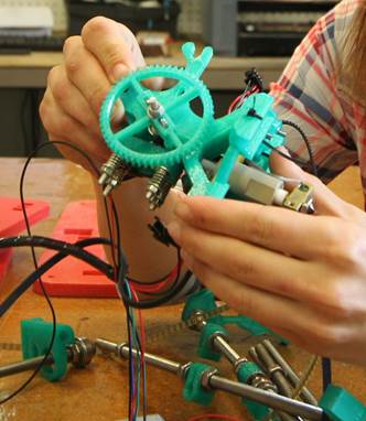 doodler though, as it does not produce a steady stream of plastic
reliably.
doodler though, as it does not produce a steady stream of plastic
reliably.
I also disassembled two CNC machines for this
project, an old MTM snap from a previous fab academy course, and a reprap 3D
printer, specifically a Durbie Prusa Mendel. Both were tricky to disassemble. I
had to use a variety of wrenches and pliers. I surprised myself by being able
to pull apart the MTM snap's thick plastic panels. Both machines had multiple
belts. Gabriel Ewing took over for me when I cut my finger on a sharp bit on
the Mendel. Virginia McCreary worked on obtaining the file to laser out our
cardboard. Cardboard is a very useful thing to have around, fortunately we keep
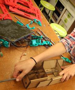
lots of it in the lab for various prototyping. We all took a stab at assembling
the cardboard housing. Then I built the
second stage, taking care to fold over the cardboard bits so it would be
secure. Virginia had some great pointers, such as using hot glue to stabilize
the stages. Our cardboard was not the recommended thickness so it didn’t fit
seamlessly at first. Once it was assembled with parts from the old 3D printers,
I checked up on my mates to see what sort of progress they had made creating a
code to move the stepper motors. They had wired the stepper motor to the
gshield and 3 wires to the Arduino Uno to the gshield, one for direction, one
for step signal, and one for enabling. I learned that this was a simple
process, as enabling drivers can be done by setting pin 8 to ground. This is 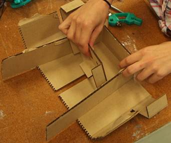 represented in code as "digitalWrite 8,
LOW". The stepper's direction is decided by the high or low voltage on the
direction pin. Jeff Putney completed an I2C code to send commands to the
Arduino Uno, by figuring out how to enable to the General Call! This discovery
had yet to been included in the I2C Arduino libraries! The ATmega has support
for the I2C, but is represented as its Two Wire Interface. To enable the
General call, we had to insert this code:
represented in code as "digitalWrite 8,
LOW". The stepper's direction is decided by the high or low voltage on the
direction pin. Jeff Putney completed an I2C code to send commands to the
Arduino Uno, by figuring out how to enable to the General Call! This discovery
had yet to been included in the I2C Arduino libraries! The ATmega has support
for the I2C, but is represented as its Two Wire Interface. To enable the
General call, we had to insert this code:
TWAR
= 0x03;
With
this valuable code, we were able to send instructions to each Arduino
individually, then direct them to start moving altogether. Each node can
receive a couple of instructions; individual
control, speed, direction, and number of steps, and the other is the synchronized move 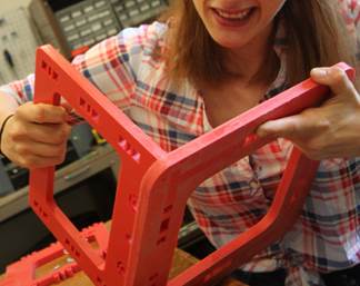 command that makes all nodes move at once.
 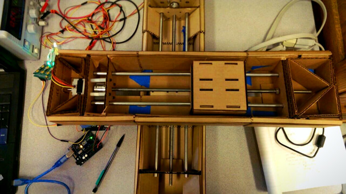 Finally, Colten Jackson modified a processing example
to create an interface to easily control the machine. This code is quite neat
in that you can draw with a stylus onto a pad, and the x & y coordinates of
the line were read by the machine as a new position for the stepper motors to
go. Here is a video of
the project! The end result worked, but it could have worked better. If we were to improve upon this design we
would do two things. One, queue multiple instructions, so there would be no
pausing between commands, and two, add feedback to the node so we would have a
smarter machine all around.
Finally, Colten Jackson modified a processing example
to create an interface to easily control the machine. This code is quite neat
in that you can draw with a stylus onto a pad, and the x & y coordinates of
the line were read by the machine as a new position for the stepper motors to
go. Here is a video of
the project! The end result worked, but it could have worked better. If we were to improve upon this design we
would do two things. One, queue multiple instructions, so there would be no
pausing between commands, and two, add feedback to the node so we would have a
smarter machine all around.